For most of us Dolphin owners dealing with a mast support issue, how we proceed depends in large part on whether you have, or plan to have, a 2 cabin open layout like my Marionette (http://www.dolphin24.org/marionettes_vberth.html) has, or a full bulkhead with a closed off, or partly closed off forward cabin and/or a separate athwartship enclosed head. In these latter cases, a mast strut can be in incorporated into the bulkhead structure. Personally, I like the strong overhead arch approach that provides a larger open feeling - we have a sketch of the arch on the site at http://www.dolphin24.org/technical_Wood_Arch.html - but there are other considerations
Passage is undergoing a major restoration (slowly - going on 8 years!) and will have a closed off forward cabin with a solid door. Why has been a subject of much discussion - but it comes down to this - the boat will be set up primarily as a day sailor/racer, AND, she will have a proper head - spacious and private for changing clothes and other needs important for the fairer sex.
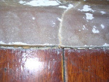
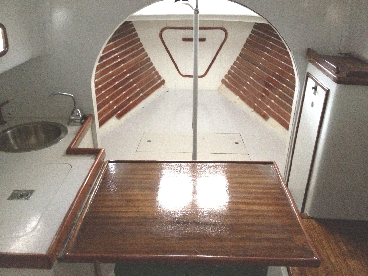
Passage has a 5/8 " plywood panel separating the 2 cabins. This is fiberglass tabbed to the cabin ceiling and the hull sides. A large oval cutout in that panel opens up the V-berth from the main cabin. See below.
Note: That triangular plywood box up in the bow is a dummy fabrication I made to check out size and fit for the holding tank I have in Marionette. I expect to use the same model for Passage.
|
|
|
fiberglass tabbing |
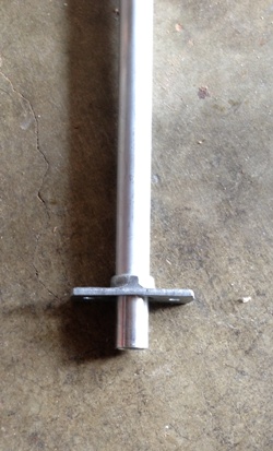
aluminum tube strut |
compressed fiberglass |
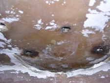
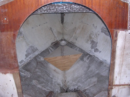
The fiberglass tabbing of the panel has a crack in it at the top - picture above left. This is under the aft part of the outside hinged plate that the mast sits on. Centered in the opening was a 60" long, 1 5/8" OD, 1/4" wall, aluminum tube strut - center picture. The S&S' # 1497 drawing spec for the mast strut was a 1 1/4" standard aluminum pipe.The strut fit into a standard pipe fitting centered under the mast just forward of the bulkhead. The right picture is actually upside down - this fitting was supporting the cabin roof. It seems to have partially compressed the solid fiberglass of the cabin roof at the aft end.
|
|
|
note indent in sole |
support under sole |
corroded strut |
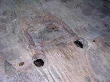
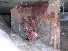
The bottom of the pipe ended in a square fitting (which I can't find) mounted directly on the wood cabin sole which was deformed from the load - see picture above left. I never did find out what those 2 holes in the sole were for - maybe drain holes. The area under the sole at this point (center picture above) is supported by a 4-5 inch high Y shaped glass covered plywood structure tabbed to the fiberglass hull and bilge. That loose piece of glass looks like an attempt to cover and retab one section. Despite is appearance it seems solid enough. Its awkward to reach but I should be able to make it look pretty - and even stronger. The aluminum strut (picture above right) and its sole mounting plate fitting (the one I cannot find), both had suffered a lot of electrolysis deterioration. This seemed to be making the tube shorter...
I wanted a strut that I could encase in a strong bulkhead and to which I could fasten the existing wood bulkhead structure. A quite conservative rule of thumb I got from John Fox at FCS Design is that mast compression loads are about 2X displacement - so on a 4500 lb displacement Dolphin - that's 9000 lbs, nearly twice the thrust load that Rod Stephens has in his September 16, 1965 load calculation letter http://www.dolphin24.org/technical_arch_load_calculation.html
A related issue is that the system has to be able to withstand side buckling - a potential problem with a thin wall aluminum tube (the crushed beer can example). The mental image here is a 200 lb guy getting a beer down below, suddenly lurching against a free standing post - whether aluminum or wood. That lurch was probably directly related to near peak loading on the mast heeling hard to leeward - so maybe a good healthy safety factor is in order.
An end grain loaded oak post can handle a 4000 PSI load so a 2" round post can handle about a 12000 lb load. A 2" square post - nice for fitting into a bulkhead structure - can handle a larger load - 16,000 lbs. John Fox recommends not going below a 2" round post because of buckling risk. I checked this out with Bruce Johnson at S&S and he said, without doing the actual structural calculations, a 2" square oak post bonded to a structural bulkhead would be more than ok.
I am planning that the new structural bulkhead would be a 1/2 ' marine plywood panel, epoxy bonded to the existing 5/8" panel and fiberglass tabbed to ceiling and hull, mechanically fastened to the sole, and bonded and screw fastened to the post. A problem with oak is it can be difficult to get good epoxy bonding so mechanical fastening is a good idea for supplemental fastening to oak..
I am certain there are readers who will take firm positions on the question of Red Oak or White Oak. This is a very complex and interesting debate and waaaaay over the top for this project. After reading an article in Wood Technology in Wooden Boat (May/June 2005) by Richard Jagels, I think either would work well, assuming good quality straight grain wood from a reputable supplier.
An interesting related matter is the end plates into/on which the post will rest - under the mast on top of the post and on the sole/bilge support structure. Those plates need have at least the same compressive strength as the end grain post otherwise they will deform as the above pictures clearly demonstrate. Typically, if made of wood, these plates are maybe 4" square to spread the load, and would present side grain to the load which is much weaker than end grain. I bought some Purple Heart wood which is much stronger and denser than oak and am thinking about using it for these plates. I am also thinking about using it for the post itself. More on this later.
Some early Dolphins used a removable aluminum strut that had a screw jack built into it. Andy Anderson's Tigress used this system only when racing. The tube/jack would be tensioned against the center of the arch in the cabin top and on a reinforced sole. This would prevent any downward mast movement and keep the shrouds at full tension.
More input/discussion on this subject is welcome - a good place for a discussion would be the Forum and your webmaster will put up an invitation there.
*****************************
March 11, 2014. Jerry Slaughter has been working on restoring ROWDY, Marcot/O'Day #5. Here is his mast step (email excerpted from ROWDY's home page)
I built a compression post for ROWDY.
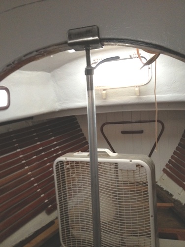
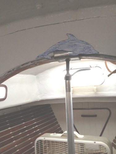
I used 3/4 inch, thick walled aluminum for the post, made up a slip-fit flange for the base and made a 2 1/2 inch saddle out of flat plate with a 1/2 inch threaded rod welded in the center. I'm using an adjustment nut followed by a lock nut to hold the adjustment. I haven't decided whether to use the nut with the arm or a wing nut. I thought of dressing up the saddle with a couple of dolphins since I had some acrylic left over. It should look nice once painted. The post is easily removable if I need more room getting in and out of the v-berth.

**************************
November 20, 2018. Mark Steinhilber is a marine architect who 'grew up' on his dad's Dolphin, Rascal. Over the website years Mark has offered his insights on many Dolphin projects. Here is his comment on the interior mast support project in Mike Gooch-Breault's (rejuvenated restoration of Passage
I'm looking forward to the main bulkhead re-design, but ultimately I think of the KISS design principle; keep it simple. It would be nice to have a private stateroom forward and nice to have a permanent support directly beneath the mast with a doorway to the left, but it is a small boat and an already small cabin with crouching and crawling headroom.
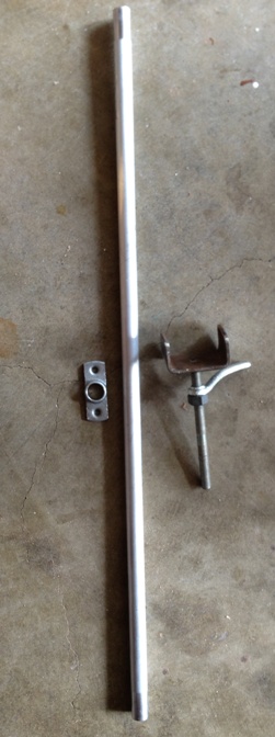
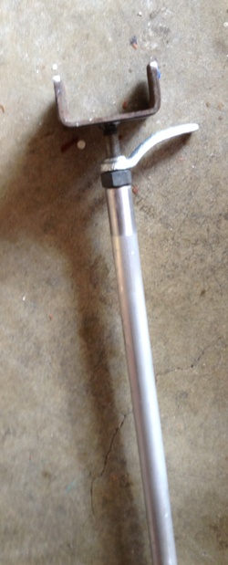
A removable mast support is easy to make with an aluminum tube and some threaded rod, just like a boat yard jack stand has. With some handles or bars welded on to a nut, you don’t even need a wrench and can take the support out for easier access to the vee berth. So many of the older Marscots and Lunns ended up with this solution because it was an easy build.
Ours was aluminum tube, probably from a broken spinnaker pole, a big bushing, a stainless nut and threaded rod, and a stainless u channel welded to the end of the threaded rod. We drilled a hole in the cabin sole and let the tube land right on the glass keel deadwood. I think there’s pictures of this in Rachel K’s and Dol Fyn’s pages.
******************************